403
TECHNICAL SECTION
SYNCHRO BLOCKER RINGS – Although there are other related parts to the synchronizers in the transmission,
there are 3 aspects to be sure to check. The first 2 are the obvious that most people understand – the "teeth" on the gear and brass blocker ring that
must mesh. The point on the end of each tooth is nearly needle sharp. They can be somewhat blunt and still work but I do not know what should be
considered the allowable tolerance. In theory, these pointed teeth (wedge shaped) make contact and mesh by the wedge shapes sliding together. This
then assures gear alignment so they may engage. However, they cannot do this effectively unless the rotation of one of the units is slowed down or
stopped. This is why the inside of the blocker ring is tapered. I also assume the "thread" like machining on the inside is for lubrication and to help in
the braking action. They are forced onto the steel cone shape and slow the rotation like a brake. Once they have worn too much they will not be able to
stop the rotation. The "teeth" then have to do more of the "synchronizing" and the sharp points quickly become blunt. You can easily tell by hand if your
blocker rings have any braking power left. I am afraid I do not know how much wear is acceptable or how to tell how much "life" is left. If someone can
tell me a way we will pass it along.
Trans Bearings – explained or not!
We've been trying to figure out exactly what GM was doing with
transmission bearings, especially in regards to the "shields". In
checking into that we also found that the replacement bearing quality
varies greatly. We believe the following correct. If you have additional
info., please let a tech person know. The "shield" for the front bearing
originally faced the inside of the trans. and the "shield" of the rear one
faced the differential. However, when bearings were substituted by Delco,
it appears they felt it didn't matter and maybe it doesn't! Also they are
no longer consistent on the part number on the "shield". One person
believes the "shield" may affect bearing life going up and down hills.
DIFFERENTIAL IDENTIFICATION Also see page 389.
1960-63 – 4 transmission bolt holes, side yokes slide right out. No holes drilled dead center on bottom.
1964 CARS – Like 1960-63 except has a cut out with 2 drilled holes dead center of bottom for the leaf spring.
1965 CARS – 4 transmission bolt holes, yokes are bolted to differential, 4 holes each side where "struts" bolt to it.
1966-69 CARS – Like 1965 except 6 transmission bolt holes.
It "snapped" and Stopped! – It doesn't matter what gear I put it in - it just doesn't move! I really wasn't "pushing it". We hear
this description at least once a month and usually it's due to the differential spyder (pinion) gears disintegrating. Jack the car up with transmission in
neutral and engine off. Have a person at each rear wheel. Turn one wheel and see if person at the other wheel can feel any movement or hear the gears
grinding. If there is no movement the Spider gears are probably "gone".
1965-69 DIFFERENTIAL YOKE PLAY – A slight amount of in and out play is normal on the 1965-69 differential yokes. I haven't seen any factory spec. If
yours "seems excessive" it is usually due to wear on the "nut" (#57) and the shaft (#56) on page 125.
SEALS – REMOVING & REPLACING
These hints should help. Also refer to the Shop Manual.
BELLHOUSING – The bellhousing must be removed (have a new gasket). Carefully tap the old seal out. Check the crankshaft gear seal area
for a groove. If a groove is worn even a new seal may leak. Replace gear or use our spacer (C5311, page 7A) which will place the seal in a slightly
different area. Carefully and evenly tap new seal in (must be installed from engine side!)
TRANS. SELECTOR SHAFT – (Shifter Shaft)
REMOVAL – The original seals had a neat metal lip that made it easy to pry out with a screwdriver. If it does not have that style use a hooked tool
or if worse comes to worse carefully drive a screwdriver into the seal. It may push in a little but should not give too much trouble.
INSTALLATION – Clean shaft of dirt, rust, or nicks. Carefully push seal to case and then evenly tap it in until it is flush with outside of transmission.
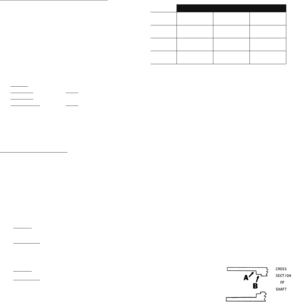
INPUT SHAFT SEAL – (Throw Out Bearing Shaft Seal)
This seal is often overlooked but must be replaced. The seal fits into Area "B" and a retainer (like a large lockwasher) fits against it to Area "A".
REMOVAL – Pull out the retainer and then the seal with a hooked tool.
INSTALLATION – Clean inside of shaft. Be sure "lip part" of seal goes in first. When seal is in place, carefully
tap seal with deep socket until it seats in place (look in with a flashlight). Now carefully install retainer
(if old one is used, spread apart enough so it will stay in place). Use socket to carefully drive in until it
seats against the seal.
FITS SHIELD FACES QUALITY
C1672
61-69 Fr ont
61-65 Rear
"wrong" way
matter?
Good
C1673
61-69 Fr ont
61-65 Rear
"wrong" way
matter?
Excellent
(best)
C1675
61-69 Fr ont
61-65 Rear
Original
Direction
Fair
C8459
$ SAVER
61-69 Front &
62-65 Rear
Either shield
removable
Good
2 SEALS – See pg. 124
For new shafts that are machined deeper
at AREA "B" to accept 2 seals.
;


 Prev
Prev 
