401
TECHNICAL SECTION
Condensor Connections – 1960-64 generator to the armature terminal
Sketch shows condensor at coil. 1960-64 Voltage regulator to "Bat" terminal
NEW PLUG WIRES SPARK in the dark?
A slight (almost static type spark) is common. Energy is transferred capacitively to the wire surface
in enough voltage to appear visible. If a bright blue-white spark is observed going from a wire to the engine
shroud, then there may be a true insulation break down.
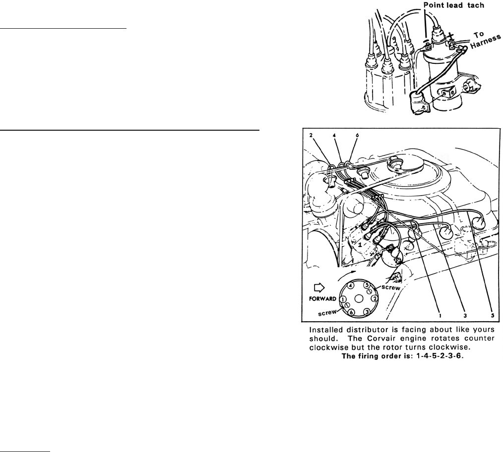
DISTRIBUTOR INSTALLATION
First step is to get your engine into TDC with the #1 cylinder. This is accomplished by
removing the #1 spark plug and rotating your engine over by hand. It is easiest to do this
with all of the plugs removed. Turn the crank until the timing mark lines up with "O" on the
rear engine housing. Now take a new unsharpened pencil and gently slide it down in to
the #1 plug hole. The pencil should only go in until it touches the piston, approximately
1–1 1/8". If it goes in more than 2", you are not on TDC. You must now rotate the motor
one full revolution to again bring the timing mark to "O". This time as you are turning the
motor counter clockwise to TDC you must place a finger over the plug hole. As you are
rotating to TDC, you should feel a building of compression against your finger. If not, you
will need to rotate the engine one more time to get onto the compression stroke. The
piston should now be at top of its stroke on the #1 cylinder and the pencil will only go in
1–1 1/8".
Another method of obtaining TDC for #1 cylinder is to remove the right side valve cover
and rotate engine until you see the #1 intake valve closing and continue rotating until the
timing mark lines up with the "O" on the rear engine housing. Both of these techniques
will bring your engine to the point where you can install the distributor.
Now you need to line the distributor up to the closest position for final installation. The
vacuum advance will be pointing toward the right rear corner of the car. Now rotate
the rotor shaft with rotor installed to the #1 position and then turn the rotor counter
clockwise, as viewed from the top of the distributor, approximately 1/3 of the distance
toward #6 plug wire location. This will compensate for the gear mesh when installing.
A. At this point you need to use a flashlight and check down in the bore of the rear engine housing to see if the oil pump gear slot is lined up
with the approximate same location as the end of the distributor shaft. If not, use a long screwdriver to turn the slot in oil pump shaft to line up
with the distributor shaft.
B. Now gently set the distributor down into its bore in the rear engine housing. You will note the rotor now turning clockwise as you drop it in. You
may have to slightly rotate the rotor shaft to help the gears line up. Once the dis tributor is seated down, the rotor should be in the #1 firing
position or at least appear close. You are now ready to secure the distributor clamp and do final timing adjustments.
To start engine: Set your points to about .017 when on a cam lobe. As you rotate the engine the points should just start to open at about 10 degrees.
This will be close enough to get running. If car just starts and idles "okay" but just won't rev up you may have the distributor installed 180 degrees off.
Remove and try again.
RUN ON REGULAR GAS! FEEDBACK WANTED
Many of you are trying all sorts of modifications to make your Corvair engine so it can run on regular gas. We would like some feedback as to very
basically what you did, if it ran on regular, and if there was much power drop. Most Corvairs seem to run OK with today's high octane gas.
These have been our findings to date for 110, 140, & Turbo.
THICKER HEAD GASKETS OR BASE GASKETS (SEE PAGE 7)
The stock cylinder base gasket is approximately .015. The stock head gasket is approximately .032. Most people have claimed "no pinging" if you add
.020 to .030 above the stock thickness. This can be done at the head gasket or cylinder base (or through a combination of these).
CYLINDER BASE – It can be done here by "stacking" a stock gasket and our C1180 (.022) OR C1180X (.032)
HEAD GASKETS – We offer copper head gaskets in .032 (stock), .042 (gain .010), or .052 (gain .020). Copper head gaskets can also be
"stacked" if necessary.
If the head gasket surface has to be "cleaned" up by machining (say .010), you will have to gain that back too. You will then need to add .030 to .040
beyond stock.
UNLEADED GAS – According to a publication from GM, the Corvair valve seats were good enough quality (our replacements are too) to be
used with unleaded gas. We suggest if you are doing a valve job that you seriously consider our manganese bronze guides, at least for the exhaust valves.
Our "bronze" guides are made from the same material as used in current day cars. There have also been reports of valve head wear. Your best choice for
this is to replace your valves with our new alloy valves – the BEST on the market. Other than that, try to eliminate any pre-ignition as quickly as possible.
You may need to run 89 or 92 octane.


 Prev
Prev 
